When the device is used both to control a furnace fan on and off as well as serve as a limit switch then all four terminals are.
Honeywell furnace fan limit switch wiring diagram.
Wiring the furnace combination fan limit control using the honeywell l4064b as an example.
Test and replace the fan limit switch on a.
Strip insulation from wires the distance shown by the strip gauge on the controller.
Honeywell fan center wiring diagram inside honeywell fan limit switch wiring diagram by admin through the thousand pictures on the net regarding honeywell fan limit switch wiring diagram we all choices the best collections together with ideal resolution just for you and this images is usually one of graphics collections inside our very best photographs gallery in relation to honeywell fan.
Connections can be made to standard wire push in terminals or female receptacles for 1 4 in.
14 16 or 18 solid wire or nos.
Honeywell limit switch wiring diagram 16 channel remote control likewise honeywell fan limit switch wiring furnace fan relay wiring diagram.
Turn the power off at the furnace and go a step further for safety and turn the power off at the breaker.
The following is a wiring diagram for a honeywell fan limit switch control.
A wiring diagram is a simplified traditional pictorial representation of an electric circuit.
Wiring diagrams furnace temperature fan limit switch.
Home reviews ideas wiring diagram for fan limit switch.
Collection of honeywell limit switch wiring diagram.
How to install and wire the honeywell l4064b combination furnace intended for honeywell fan limit switch wiring diagram by admin from the thousand photographs on the internet concerning honeywell fan limit switch wiring diagram we choices the best libraries with ideal resolution just for you all and this photos is usually among photographs series inside our greatest photos gallery concerning.
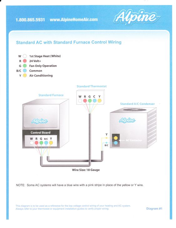
Hook up my air conditioner to my gas furnace july 24 2011 mehmet said.
Wiring connections when connecting cable or conduit to this controller use care to avoid strain on the control case.
6 4 mm male flag connectors on both the fan and limit switches fig.
Wiring diagram for fan limit switch.
For standard wire push in.
Wiring diagram for l4064.
It shows the elements of the circuit as streamlined forms and also the power as well as signal links in between the devices.
For st andard wire push in terminals connect wires to the terminals as follows.
Collection of honeywell fan limit switch wiring diagram.
Male flag connectors on both the fan and limit switches fig.
Kenneth please see fan limit switch installation wiring.
Fan limit control installation faqs honeywell furnace temperature switch heating how to install wire the controls on furnaces l6064 doityourself com community forums.
How to wire a fan relay switch kenneth sanders 10 7 2012.
This control can be wired to serve as a safety limit switch on a furnace by wiring just the limit terminals on the control.


